Email Us

FAQ

Whether Unicore’s products support BDS-3?

Yes, Unicore’s products all support BDS-3.

What is the inertial navigation deviation of UM220-IV INS module for half an hour?

There will be 10 to 15 meters deviation for the inertial navigation with odometer input after running for 3 kilometers. The actual accuracy of inertial navigation may vary due to the difference in application environment and the deviation indicators.


The deviation of pure inertial navigation of Unicore products is 5% of the driving distance (without odometer, about 5 meters deviation for 100 meters distance). With the odometer input, the accuracy will be improved and maintains precise for a longer time.

What is the function of the “odometer” of the UM220-INS module besides improving the positioning accuracy?

UM220-INS module is an integrated navigation product, which relies on the internal MEMS to implement positioning when there are no satellite signals detected. The pulse information provided by the odometer serves as a reference for velocity and direction, helping the module to correct errors and improving the navigation accuracy.


There are requirements for the odometer input signals specified in the User Manual and reference circuit in the Hardware Reference Design.


Additional information: UM220-INS has ADR (Automotive Dead Reckoning) version and UDR (Untethered Dead Reckoning) version, of which the former has a larger shipment volume and needs the odometer to improve its accuracy, while the latter does not.


If your vehicle already has the odometer interface and data to use, you may choose the ADR version. If you don’t need to combine the GNSS data with the position information collected by the sensors installed on the vehicle body and wheels, you may choose the UDR version.

What is the function of the 1PPS signal? Under what circumstances is it used? How to deal with it if I don't use it?

The 1 Hz pulse signal of our timing products such as UM220-IV L has a higher accuracy and can be used for timing. The pulse signal of non-timing products such as UM220-INS has a lower accuracy and lower stability, about millisecond level, which cannot be used for precise timing.


A pulse per second (PPS) is an electrical signal output by a device once per second. Millisecond-level PPS signal can be used for simple timing, heartbeat detection, event trigger, and other applications, which can be defined by users. If you don’t use the PPS signal, you can leave the pin floating.


What is the reason if there is no data output or output messy code from the UART of UC6226NIS chip?

There are three possible reasons if no data output from the UART of the UM220-IV N module or UC6226NIS chip after connecting to a computer.


1)Reason one: Abnormal power supply

Use a multimeter or an oscilloscope to check the power input pin of the module or chip, to test whether the power supply or voltage is normal.


2)Reason two: The voltage level has not been converted

The voltage level of the UART of the positioning module and chip is LVTTL, and the high level is 3.3/1.8 V, while the level of the UART of a PC is usually RS232. Therefore, level conversion is required in order to ensure normal communication.


3)Reason three: Incorrect use of UART or baud rate

Check whether you have used the right UART and baud rate. The frequently used baud rates of the positioning modules and chips are 9600, 115200, 230400, and 460800.


What is the reason if the positioning time is long, positioning results inaccurate, or the module cannot fix the position?

1)Reason one: You might have used an active antenna but not fed power to the antenna.

After the module is powered on, use a multimeter to check whether the antenna interface on the board is fed power that meets the antenna specifications.


2)Reason two: Insufficient antenna gain

You might have used a passive antenna but not designed external LNA and SAW.


You might have used an active antenna with low gain.


3)Reason three: Interference

The use of external LNA and SAW without shielding will cause external electromagnetic interference to seriously affect the reception of satellite signals.


Insufficient electromagnetic design of the whole machine causes in-band interference to enter the antenna through radiation and affect the reception of satellite signals.


Why does the dual-frequency product UM626N use L5 rather than L2?

GPS L2 was a military-only frequency in the early days, and L1 and L5 were civilian frequencies. In the civil field, L1 is the first frequency that has been used. Due to the accuracy problem, the L5 frequency is added to realize dual-frequency positioning to eliminate ionospheric errors and improve accuracy. The frequency of the L5 signal is higher. Usually the L1 signal is used to lock the satellite and L5 signal is used to calculate the precise position.


What is the recommended distance between the two antennas when using the heading function of UM482?

There is no limit to the distance between the master antenna and slave antenna of UM482, and even zero baseline can be used for heading. The baseline length and heading accuracy are inversely proportional, which is, the longer the baseline length, the higher the heading accuracy. So far, the heading accuracy of the dual-antenna UM482 is 0.2°/1m baseline, and the accuracy is inversely proportional to the baseline length, such as 0.1°/2m baseline, 0.05°/4m baseline, and so on.


​The positioning accuracy of UB4B0M in the User Manual is centimeter level, can this module achieve millimeter-level accuracy?

The RTK positioning accuracy is “2 cm + 1 ppm”, where the 2 cm refers to systematic error, and 1 ppm refers to proportional error which depends on the distance between the base station and rover station. Assuming that the distance between the base station and the rover station is 10 km, then the error is 2 cm + 1000000 cm * 0.000001 = 3 cm. Millimeter-level accuracy can be achieved through algorithm post-processing.


What is the maximum height limit for the antenna of the UM4B0 module?

In accordance with the current industry standard, the dynamic application range of high-precision boards is that the maximum positioning height is 18000 m, the maximum speed is 515 m/s, and the acceleration is less than 5 g.


Which RTCM version should I choose when I configure the base station, and how can I configure it?

The RTCM versions include 2.3, 2.4, 3.0, 3.2, and 3.3.


CMR.RTCM2.X is less used now, because it is not compatible with Galileo and BDS RTK differentials. It only added the pseudorange differential corrections for Galileo, BDS, and QZSS in Version 2.4, and the accuracy is at sub-meter level. Compared with RTCM 3.0, RTCM 3.2 added multiple signal messages (MSM1~MSM7) of pseudorange and carrier phase corrections, as well as the output of DGNSS data for Galileo, BDS, and QZSS observations. RTCM 3.3 added NAVIC/IRNSS EPHEMERIS 1041, BDS EPHEMERIS 1042, GALILEO I/NAV EPHEMERIS 1046, SBAS MSM 1101~1107, and NAVIC 1131~1137 on the basis of RTCM 3.2.


UNICORE base station supports the output of GPS 1071~1077, GLO 1081~1087, GAL 1091~1097, QZSS 1101~1107, and BDS 1121~1127 in RTCM 3.2, and the decoding supports 1073~1077, 1083~1087, 1093~1097, 1103 ~1107, and 1123~1127.


Recommended configuration of base station (RTCM 3.X)

Mode base [latitude] [longitude] [height] (Default is altitude; if you want to use the ellipsoidal height, input “config undulation 0.0”)


rtcm1033 COM2 10 Receiver type of the base station


rtcm1074 COM2 1 GPS pseudorange and carrier phase information

What is the impact of discontinuous transmission of differential data or excessive delay on RTK solution?

The more stable the transmission of differential data is, the greater the help for differential positioning, and the more stable the accuracy will be. If the packet loss is very serious on the transmission link of differential data and the differential age usually exceeds 15, the reliability and accuracy of RTK will decrease.


RTK eliminates ionospheric errors, tropospheric errors, satellite orbital errors, and satellite clock bias through the correlation of errors between the base station and rover station, thereby achieving centimeter-level positioning accuracy. If the transmission of the base station data is interrupted, the correlation between the rover station observations and the aforementioned errors in the base station data tens of seconds ago will be weakened, and the longer the time, the weaker the correlation, and then the positioning accuracy will drop fast.


Ordinary receivers will not be able to provide RTK service after 20 seconds since the interruption of the differential data transmission. But Unicore's RTK KEEP technology, which uses models and estimation to eliminate the satellite orbital errors, clock bias, ionospheric and tropospheric errors, as well as other factors that affect the positioning results, can maintain centimeter-level accuracy for more than 10 minutes after the transmission of the differential data from the base station is interrupted. This greatly improves the availability of RTK service, especially for applications such as UAVs and forestry operations, where radio or wireless network communications are often interfered or blocked.

Why sometimes RTK cannot be fixed at noon?

For areas with relatively low latitudes, the ionosphere is more active at noon. Even if the base station and rover station are under the open sky, when the baseline is more than 10 km, it is difficult to get an RTK fix. This is a common problem for measurement receivers, because the ionospheric error may be around half a cycle, so RTK cannot be fixed.


Unicore’s RTK technology can utilize the observations of all constellations and all frequencies. Even if the base station (or network RTK virtual base station) you use does not have the function to track all constellations and all frequencies, Unicore’s RTK technology can still use the satellite signals that have not been observed by your base station to do RTK calculation, which greatly improves the availability, reliability and precision of RTK positioning. At the same time, the RTK algorithm makes full use of the advantage of all-constellation and all-frequency observations, with perfect cycle slip detection and repair technology, as well as the multi-system multi-frequency narrow-lane, wide-lane, and ultra-wide-lane ambiguity combination technology, by means of the multi-frequency combination method and model/parameter estimation to eliminate the errors caused by the ionospheric delay, tropospheric delay, and multi-path effect, which greatly improve the initialization time, reliability and accuracy of RTK. So far, Unicore’s RTK technology can use more than 60 satellites in real time, and the number is still increasing. Thanks to the optimized RTK algorithm, matrix operation algorithm, and hardware-accelerated floating-point operation on Unicore’s chip, the RTK update rate can reach more than 50 Hz even if there are more than 60 satellites with multiple frequencies participating in the RTK solution, which perfectly meets the needs of high dynamics, high precision, high availability, and high reliability.


Will it affect the normal operation of the rover station board if I transmit two channels of differential data at the same time?

In order to ensure the continuous transmission of differential data, some engineers transmit two channels of differential data to the board at the same time. If the data are transmitted through two different serial ports, there will be no problem, since the program has protective design inside, which only decode the data that arrives first at the serial port, and ignore data from the other port.


What is the difference between the positioning accuracy unit RMS and CEP?

There are three units of the positioning accuracy: CEP, RMS, and 2DRMS. RMS is 1 sigma or 1 standard deviation; if the result is unbiased, the probability is 67%. 2DRMS is 2 sigma or 2 standard deviation, and the probability is 95%. The conversion rules between the three units are as follows:


CEP × 1.2 = RMS


CEP × 2.4 = 2DRMS


What is the relation between TX level and VDD_IO?

The TX level is consistent with the VDD_IO voltage.


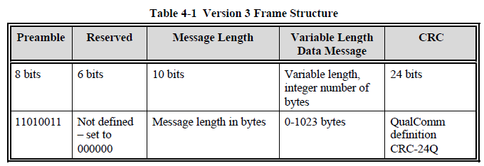
The binary message structure of RTCM3.X

the-binary-message-structure-of-rtcm3.x.png


Does the antenna of the UB4B0M module need to be powered separately?

The antenna of the UB4B0M module uses the same power supply as the LNA, which is provided by the module itself and does not need a separate power supply. The power supply circuit on the development board is prepared for other modules that need to be powered separately.


As shown in the table below, how to understand the Iout of UM482? And for the parameter’s thresholds, does that mean to keep the output current constant, and the voltage should be within the specified range?
ParameterSymbolMin.TypicalMax.UnitCondition
Low level output voltageVout_low0
0.45Vlout=4mA
High level output voltageVout_highVCC-0.45
VCCVlout=4mA


1)The meaning of Iout:

When the output voltage of GPIO is low level, it allows 4 mA current input from the outside, which will not affect the service life or reliability of the module.

This places requirement on the resistance of the pull-up resistor. If the resistor is 1 kΩ and it is connected to a 3.3 V power supply, when GPIO is low level, the external current flowing into the pin will be 3.3 mA. If the resistor is 500 Ω and connected to 3.3 V, when GPIO is low level, the input current will be 6.6 mA, which is higher than the requirement of Iout. Therefore, the pull-up resistor is generally required to be larger than 1 kΩ.

Likewise, when the output voltage of GPIO is high level, it allows 4 mA current output to the outside, and the requirement on the resistance of the pull-down resistor is similar to what mentioned above.

If not considering the service life of the module, the allowable current input or output at the GPIO is much greater than 4 mA.

2)About the second question, the answer is as follows:

The ideal low level voltage should be 0 V and high level should be equal to VCC.

For the UM482 module, the maximum value of low level is 0.45 V, and the minimum value of high level is VCC-0.45 V. The reason is that the voltage output will pass through a diode, which will cause a certain voltage drop. Within the temperature of -40 ℃ to +85 ℃, the voltage drop is close to 0.45 V.

The voltage drop caused by the diode is related to the current passing through it, so a limit of 4 mA current is also added as a condition.


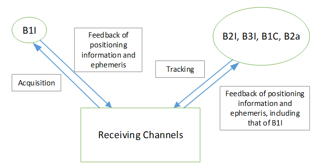
Signal acquisition process

signal-acquisition-process.png

Signal acquisition process of Nebulasll Chip

The NebulaslV chip is upgraded on the basis of Nebulasll. lt can capture and track each frequency independently.

Can the differential corrections be directly input to the serial port through a serial port line?

Here the differential corrections should refer to differential RTK corrections, and if it comes from the base station, it can be directly input to the rover station through the serial port line.


What is the meaning of V1R2Build21464 of the UB482 board?

V1R2 is the hardware version, and Build21464 is the firmware version.


A brief introduction of NTRIP

1)What is NTRIP?

CORS (Continuously Operating Reference Stations) system is a network of stations that receive and send GNSS differential corrections over the Internet. With the use of CORS, you don’t need to set a GNSS base station to send the differential corrections to the GNSS rover station. In order to visit the CORS system, network communication protocols are needed, and one of which is NTRIP (Networked Transport of RTCM via Internet Protocol).


2)Structure of the NTRIP System

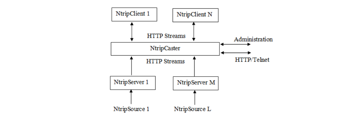
The figure below shows the structure of the NTRIP system used by CORS.


a-brief-introduction-of-ntrip.png


NtripSource is used to generate GNSS differential correction data and send it to NtripServer. NtripServer sends the GNSS differential correction data to NtripCaster.


NtripCaster is the center of differential correction data, in charge of the reception and transmission of GNSS differential correction data.


NtripClient receives the GNSS differential correction data sent from the NtripCaster after the user logs in NtripCaster.

About the RF-Baseband Integrated Design

The RF-baseband integrated design includes the design of the baseband structure, algorithm optimization, digitization of analog circuits, low power consumption design, reasonable frequency planning, optimized layout, proper isolation to reduce the interference of the digital system to the RF part, reasonable pin assignment, systematic integration of LDOs with low quiescent current consumption, and systematic optimization in test methods.


A time-domain and frequency-domain combined method and process to suppress narrowband interference

The traditional methods to suppress narrowband interference mainly include the time-domain method and frequency-domain method, but both of them have certain shortcomings. In general, the time-domain method features fast convergence and good adaptability to non-stationary interference, but causes a large distortion of the correlation peak, resulting in a large deviation of measurement. The frequency-domain method features accurate spectrum suppression and small measurement deviation, but has poor adaptability to non-stationary interference. A typical situation is that for the narrowband pulse interference with the magnitude of Hertz, the frequency-domain processing method tends to generate more error codes and results in the loss of lock, while the time-domain method can quickly realize convergence and still work normally. At the moment of switching on/off, the frequency-domain method tends to generate more error codes, while the time-domain method does not have this problem. Another typical situation is that when the interference bandwidth exceeds 10% of the signal bandwidth, the time-domain method causes a large measurement deviation, while the frequency-domain method does not have this problem.


The process of the time-domain and frequency-domain combined method to suppress narrowband interference is as follows:


S1. The digital down-conversion unit transforms the signal input from the ADC to baseband in-phase (I) and quadrature-phase (Q) signals and send them to the frequency-domain anti-jamming unit.


S2. The frequency-domain anti-jamming unit applies a windowing operation to the N-point baseband data.


S3. The frequency-domain anti-jamming unit performs Fast Fourier Transform (FFT) on the windowed data to get FFT data.


S4. The frequency-domain anti-jamming unit estimates the power spectrum of the FFT data and judges the interference spectrum, and then generates the weight values of 0 and 1.


S5. The frequency-domain anti-jamming unit performs weighting process on the FFT data obtained from step 3 using the weight value calculated in step 4.


S6. The frequency-domain anti-jamming unit performs IFFT on the weighted data to get time-domain data.


S7. The time-domain data obtained from step 6 is input to the time-domain anti-jamming unit to perform adaptive filtering.


S8. The time-domain data obtained from step 6 and that obtained from step 7 are input to the data selection unit, and then the selected signals are output.


When I test UC6226NIS using AGNSS to speed up the position fix, why is the date output delayed after the positon is fixed?

The date information has nothing to do with the position fix; it is obtained from the navigation message in every 30 seconds. The position fix is usually finished within 6 seconds, so there is a high probability that no date information is given after the position is fixed. It will take a period of time to be obtained, and this time will be less than 30 seconds in normal signal environment.


CONTACT
Subscribe
Subscribe to get news updates from us
We use cookies to offer you a better browsing experience, analyze site traffic and personalize content. By using this site, you agree to our use of cookies. Visit our cookie policy to learn more.
Reject Accept